AP®︎ Physics 1: Topic 5.3 Practice Test
Prepare for your quiz, test, or the AP exam with focused practice questions on Topic 5.3 of AP Physics 1 – Torque.
Questions List
Topic 5.3
Question 1 Easy
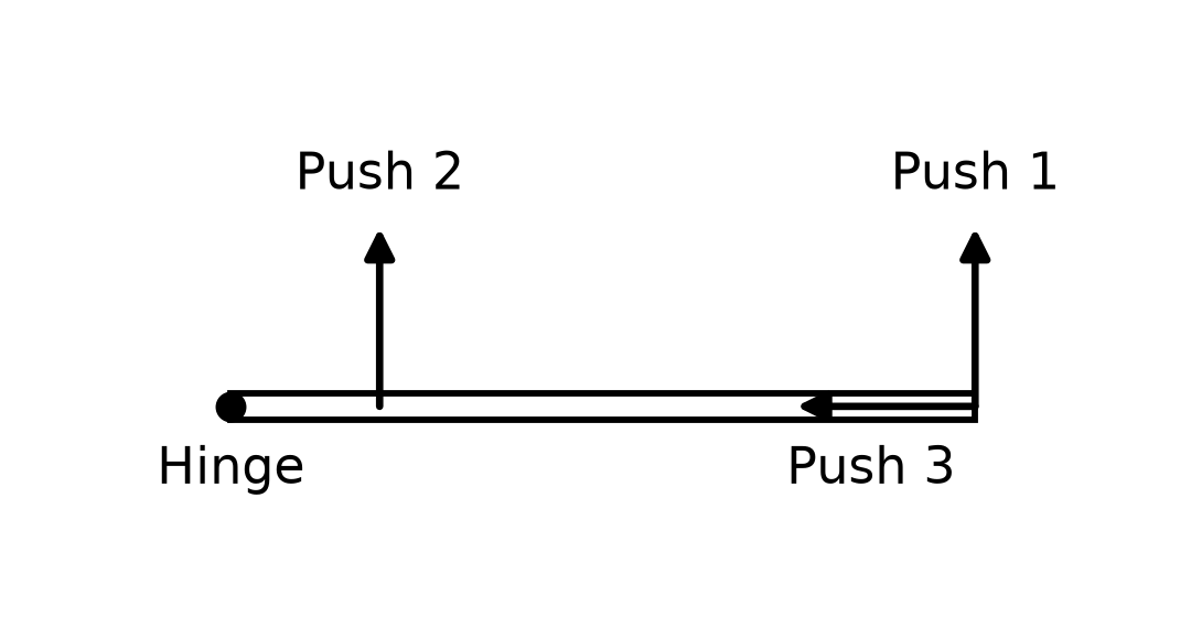
Which push exerts the greatest torque about the hinge?
What You’re Being Tested On:
Explore the learning objectives taken directly from the College Board’s AP® Physics 1 Curriculum. Ensure you’re prepared for the exact topics covered on the AP® exam, in-class tests, and quizzes, and gain confidence in your mastery of the material.

Topic 5.3: Torque
Boundary Statements official exam scope notes
- While AP Physics 1 expects students to mathematically manipulate the magnitude of torque using vector conventions, the direction of torque is beyond the scope of the course.
Learning Objective: 5.3.A
Identify the torques exerted on a rigid system.
Essential Knowledge: 5.3.A.1
Torque results only from the force component perpendicular to the position vector from the axis of rotation to the point of application of the force.
Essential Knowledge: 5.3.A.2
The lever arm is the perpendicular distance from the axis of rotation to the line of action of the exerted force.
Learning Objective: 5.3.B
Describe the torques exerted on a rigid system.
Essential Knowledge: 5.3.B.1
Torques can be described using force diagrams.
Essential Knowledge: 5.3.B.1.i
Force diagrams are similar to free-body diagrams and are used to analyze the torques exerted on a rigid system.
Essential Knowledge: 5.3.B.1.ii
Similar to free-body diagrams, force diagrams represent the relative magnitude and direction of the forces exerted on a rigid system. Force diagrams also depict the location at which those forces are exerted relative to the axis of rotation.
Essential Knowledge: 5.3.B.2
The magnitude of the torque exerted on a rigid system by a force is described by the following equation, where is the angle between the force vector and the position vector from the axis of rotation to the point of application of the force.
