Topic 5.3 Notes – Torque
1. What Torque Is
Torque () measures how strongly a force tries to rotate an object about a chosen axis of rotation (pivot).
Think of:
- Pushing a door
- Using a wrench
- A seesaw balancing
A force only creates torque if it tends to twist the object about the axis.
What torque depends on
Three things determine the magnitude:
- Force magnitude
- Distance from the axis
- Angle between the force and the position vector
Units are newton-meters (N·m).
They look like joules, but torque is not energy.
Two big ideas to lock in:
- A force at the pivot produces zero torque because .
- Not all of a force contributes to rotation.
That second idea is where the equation comes in.
2. The Torque Equation and What Each Part Means
The magnitude equation
Where:
- = distance from axis to point of application
- = applied force
- = angle between the position vector and the force
AP Physics 1 cares about the magnitude of torque, not full 3D vector direction.
Perpendicular force component
Only the component of the force perpendicular to causes rotation.
So torque can also be thought of as:
Special angles:
→ → maximum torque
or → → no torque
If you push directly toward the pivot, you get zero rotation no matter how hard you push.
This shows up constantly in multiple-choice questions where two forces have the same magnitude but different angles.
Lever arm
There’s another way to think about torque that many students find easier.
Lever arm = the perpendicular distance from the axis to the line of action of the force.
In the diagram below, the rod is pivoted at the left. The force is applied at an angle on the right, and the green segment shows the perpendicular distance from the pivot to the dashed line of action. That green length is the lever arm.
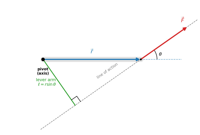
Lever arm and line of action
Then:
Longer lever arm → bigger torque.
That’s why:
- Door handles are far from hinges
- Long wrenches make loosening bolts easier
3. Identifying Torques on a Rigid System
Force diagrams for rotational systems
You analyze torque using a force diagram, similar to a free-body diagram but with rotation in mind.
It must show:
- All forces
- The axis of rotation
- Where each force is applied
For example, consider a horizontal beam pivoted at its center with forces applied at different distances:
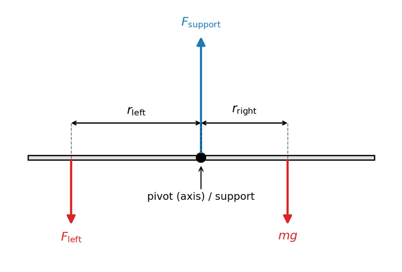
Force diagram of a pivoted beam with multiple forces
Key idea: Two equal forces at different distances create different torques.
Weight acts at the center of mass unless stated otherwise.
How to identify torques
When solving problems:
- Choose or identify the axis.
- Draw all forces.
- For each force:
- Find distance
- Find angle
- Determine the perpendicular component
- Calculate torque using or lever arm.
- Conceptually decide which way it tends to rotate.
You don’t need full right-hand rule analysis in this course, just clockwise vs. counterclockwise.
4. Multiple Torques and Rotational Equilibrium
When several forces act, each produces its own torque.
Rotational equilibrium
If:
then total clockwise torque equals total counterclockwise torque.
The object:
- Does not rotate, or
- Rotates at constant angular velocity
Typical AP setup:
- Balanced beams
- Hanging masses at different distances
- Objects supported by a pivot
A common mistake is measuring distance along the object instead of perpendicular to the line of action. Always think geometry.
