Topic 11.2 Notes – Simple Circuits
1. What an Electric Circuit Is
An electric circuit is a closed conducting loop that allows charge to move continuously because of a potential difference, usually from a battery.
Current is defined as
and in circuit diagrams we use conventional current, flowing from the positive to the negative terminal of a battery.
Closed, Open, and Short Circuits
Closed circuit
A complete path exists → charges can flow → current exists.Open circuit
There’s a break somewhere → no complete path → .Short circuit
A path of negligible resistance connects two points that normally would have a voltage difference.- Almost no potential drop along that path
- Very large current
- Other components may be bypassed
A short circuit often shows up on exams when a wire is drawn across a resistor. If both ends of the resistor are connected by ideal wire, that resistor has zero voltage across it and is effectively irrelevant.
A single component can belong to multiple loops in a more complex circuit. Loops are just complete paths that start and end at the same point.
Also remember Ohm’s law for resistors:
2. Circuit Elements and What They Do
You need to instantly recognize these and know their behavior.
Wires
- Ideal wires have negligible resistance
- Any two points connected by ideal wire are at the same potential
- Redrawing wires without changing connections does not change the circuit
Battery (DC source)
- Maintains a fixed potential difference
- Does work on charges to sustain current
Resistor
- Opposes current
- Converts electrical energy → thermal energy
- Obeys
Lightbulb
- Behaves approximately like a resistor
- Brightness relates to power
Capacitor
- Stores charge and electric potential energy
- In steady-state DC, it eventually acts like an open circuit
Inductor
- Stores energy in a magnetic field
- Opposes changes in current
Switch
- Open → breaks the loop
- Closed → completes the loop
Measuring Devices
Ammeter
- Measures current
- Placed in series
- Ideal resistance = 0
Voltmeter
- Measures potential difference
- Placed in parallel
- Ideal resistance = infinite
Variable components are shown with a diagonal arrow across the symbol.
3. Circuit Schematics and Physical Arrangement
A schematic is symbolic. It shows electrical connections, not physical layout.
Here’s a standard reference of common circuit symbols you should recognize on sight:
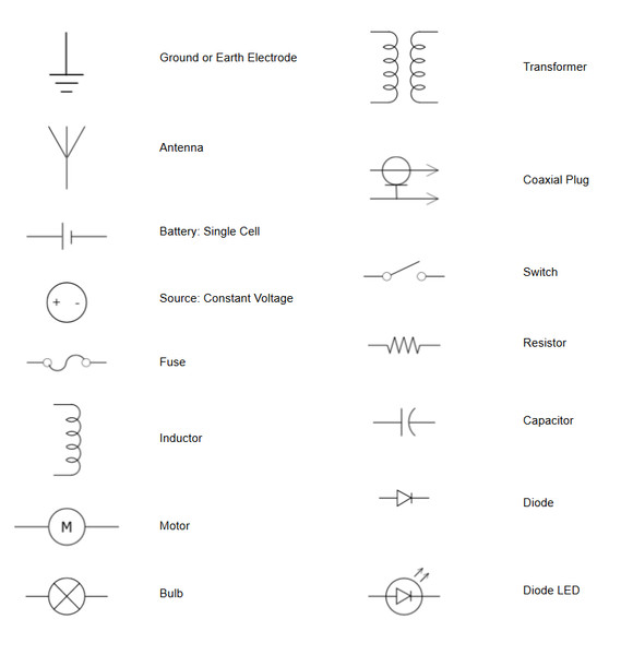
Common circuit schematic symbols
Important ideas:
- Straight lines → wires
- Zigzag → resistor
- Long/short lines → battery
- Equal parallel lines → capacitor
- Coil → inductor
- Circle with A or V → meters
The arrangement determines behavior:
- Series → components share the same current
- Parallel → components share the same two nodes (same voltage)
- A junction is where three or more wires meet
Two points connected by ideal wire are the same node. On tests, you’ll often redraw circuits to make series and parallel groupings more obvious.
4. Series and Parallel Connections
Series
Components are in series when there is only one path for current between them.
Properties:
- Same current:
- Voltages add:
- Equivalent resistance:
If one element opens, the entire path stops conducting.
Parallel
Components are in parallel when they share the same two nodes.
Properties:
- Same voltage:
- Currents add:
- Equivalent resistance:
If one branch opens, the others still conduct.
Quick Comparison
| Feature | Series | Parallel |
|---|---|---|
| Same quantity | Current | Voltage |
| What adds | Voltage | Current |
| behavior | Increases | Decreases |
| If one fails | Entire path stops | Other branches unaffected |
5. Multiple Loops and Current Distribution
In multi-loop circuits:
- Current splits at junctions
- It recombines later
- One element can belong to multiple loops
When solving:
- Identify clear series or parallel groupings.
- Replace them with .
- Reduce to one total resistance.
- Use .
- Work backward to find branch currents and voltages.
Always check:
- Current conservation at junctions
- Same voltage across parallel elements
If a near-zero resistance path connects two points, components between those points are shorted and have .
