Topic 13.4 Notes – Inductance
1. What Inductance Is
When current flows through a wire, it creates a magnetic field around it. If the current changes, the magnetic field changes. A changing magnetic field induces an emf. That induced emf acts back on the circuit.
For an inductor, we define inductance through
- is inductance
- Units: henry (H)
- The negative sign comes from Lenz’s law. The induced emf opposes the change in current.
So if current is increasing, the induced emf tries to reduce it. If current is decreasing, the induced emf tries to keep it flowing.
A helpful way to think about it: inductance is inertia for current. Current does not jump instantly in a circuit with an inductor.
A few modeling reminders for AP:
- A straight wire is usually treated as having negligible inductance.
- A device intentionally built to have significant inductance is an inductor, typically a coil of wire (often a solenoid).
Here’s the standard picture of an inductor as a coil connected in a circuit:
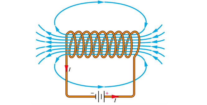
Solenoid (inductor) connected to a battery
The tightly wound coil concentrates magnetic field lines through its interior, which increases the magnetic flux and makes significant.
2. What Determines the Inductance of a Solenoid
For a long solenoid, the inductance is
- = number of turns
- = cross-sectional area
- = length
- = magnetic permeability of the core
- Air core:
- Material core:
Now connect each variable to physical intuition:
- Number of turns
.
Doubling makes four times larger. This is the strongest design factor because each turn links magnetic flux from all the others. - Area
Larger area means more magnetic flux through each loop → larger inductance. - Length
Longer solenoid spreads the field out → smaller .
Shorter solenoid → larger . - Core material
A ferromagnetic core dramatically increases by strengthening the magnetic field for the same current.
On a derivation-style FRQ, you’re often expected to combine the solenoid field with magnetic flux and Faraday’s law to justify why scales this way.
3. Induced EMF in an Inductor
Using Faraday’s law,
For a coil, magnetic flux is proportional to current. So
This tells you:
- Large → large induced emf.
- Constant current () → no induced emf.
- Larger → stronger opposition to change.
This is why flipping a switch in a circuit with an inductor can produce a voltage spike. A sudden drop in current means a large negative , which means a large induced emf.
In circuit problems, be careful with signs. The inductor’s voltage polarity must oppose the change in current, not necessarily the current itself. That detail is a common place to lose points.
4. Energy Stored in an Inductor
An inductor stores energy in its magnetic field.
Important features:
- Energy scales with .
Double the current → four times the energy. - Larger → more energy for the same current.
- Units check:
That energy lives in the magnetic field, not “in the wire.”
In circuits, this stored energy can:
- Be dissipated as thermal energy in a resistor.
- Transfer to a capacitor, becoming electric potential energy.
- Convert to other forms, always obeying conservation of energy.
On AP-style problems, you might be asked to equate to when energy transfers between inductor and capacitor.
5. Big Picture Connections for Circuits
It helps to compare elements:
- Resistor responds to current itself.
- Capacitor opposes changes in voltage.
- Inductor opposes changes in current.
At steady state with constant current:
An ideal inductor then behaves like a wire.
During switching or transient behavior, inductors control how quickly current can change. That timing behavior becomes central in RL and LC circuits, which build directly on what you learned here.
