Topic 12.3 Notes – Magnetic Fields of Current-Carrying Wires and the Biot-Savart Law
1. The Biot-Savart Law
The Biot-Savart law tells you the magnetic field produced by a tiny segment of current.
- is the current
- points in the direction of current
- points from the wire segment to the field point
- is the distance to that point
To get the total field from a whole wire:
What this equation is really saying
- Bigger current → bigger magnetic field.
- Farther away → weaker field, falling off as for each tiny piece.
- Direction comes from the cross product .
- You must add contributions as vectors.
The cross product is the heart of this topic. If you ignore direction, you lose half the problem.
2. Direction and Shape of Magnetic Fields Around a Wire
Straight current-carrying wire
The magnetic field forms concentric circles around the wire. In the diagram below, focus on the vertical wire with current upward and the circular field lines wrapping around it.
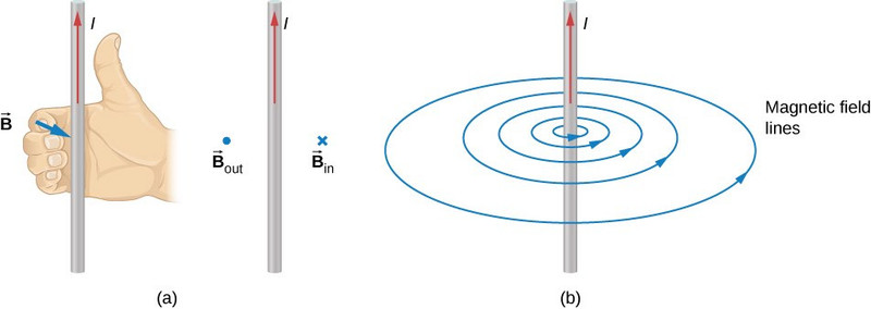
Magnetic field around a straight current-carrying wire
Key facts:
- Field vectors are tangent to the circles.
- There is no component pointing radially outward.
- There is no component parallel to the wire.
Use the right-hand rule, as shown by the hand in the figure:
- Thumb → current
- Fingers → magnetic field direction
If the current flips, the field flips.
Why circles?
From :
- The result is perpendicular to both the current direction and the radial line.
- That forces the field to wrap around the wire.
- If points directly toward the field point, then , so that segment contributes nothing.
This geometric reasoning is something FRQs love. You explain cancellation using symmetry and the cross product.
3. Magnetic Field Results You Must Know
These come from integrating Biot-Savart using symmetry.
Long straight wire
- Decreases as
- Direction from right-hand rule
- Assumes wire is effectively infinite
Students often forget this is not . The integral changes the distance dependence.
Center of a circular loop
- is loop radius
- All current elements are same distance from center
- Direction is perpendicular to the plane (right-hand rule curling around loop)
- For turns, multiply by
This is one of the most tested results in this unit.
Arc of a circle at its center
- in radians
- Full circle gives loop formula
- Radial connecting segments give zero contribution at the center
Field along the axis of a circular loop
At a point on the axis:
- Horizontal components cancel.
- Only axial components add.
The symmetry looks like this in a typical setup.
You’re expected to set up the Biot-Savart integral and use symmetry to reduce it to one component. The exam will not throw you a random messy shape.
Perpendicular bisector of a finite straight segment
At a point centered across from the segment:
- Components parallel to the wire cancel.
- Perpendicular components add.
Again, symmetry simplifies the integral. Always state which components cancel and why.
4. Applying Biot-Savart on an FRQ
When you see one of these:
- Draw the geometry clearly.
- Identify what cancels by symmetry.
- Write .
- Express everything in one variable.
- Integrate over correct limits.
- Give direction using right-hand rule.
Common trap: using degrees instead of radians in arc problems.
AP scope is limited to symmetric cases like loops, arcs, axes, and perpendicular bisectors. You’re not expected to handle arbitrary 3D shapes.
5. Force on a Current-Carrying Wire
A magnetic field pushes on moving charges. A current is moving charge. So a magnetic field pushes on a wire.
General form:
For a straight wire in uniform :
Magnitude:
- Maximum when wire is perpendicular to field.
- Zero when parallel.
- Direction from right-hand rule for .
This is the basis of motors and magnetic torque, which comes next.
