Topic 11.5 Notes – Compound Direct Current Circuits
1. Series and Parallel Connections
Everything in a DC circuit reduces to series and parallel relationships. If you can spot those instantly, the rest becomes mechanical.
Series connections
A series connection means there is only one path for charge. Any charge that goes through one element must go through all of them.
Key properties:
- Current is the same through every element
- Voltages add to equal the battery’s terminal voltage
- Equivalent resistance adds:
Adding resistors in series increases total resistance. More opposition → smaller total current for a fixed emf.
Here’s a simple single-loop example with three resistors in series:
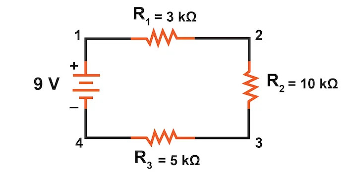
Three resistors connected in series with a 9 V battery
Parallel connections
A parallel connection means there are junctions and multiple paths between the same two nodes.
Key properties:
- Voltage is the same across each branch
- Currents split at junctions and recombine later
- Equivalent resistance satisfies:
For two resistors:
Adding a parallel branch always decreases total resistance. In fact, is smaller than the smallest individual resistor.
Here is a two-branch parallel example between nodes and :
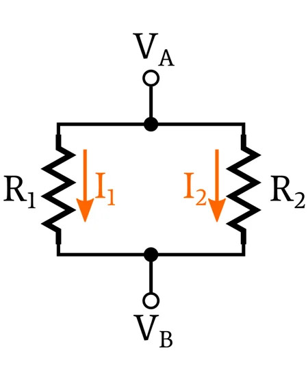
Two resistors connected in parallel between the same two nodes
2. Equivalent Resistance in Compound Circuits
A messy circuit can always be replaced by a single equivalent resistance that has the same effect on the rest of the circuit.
What you actually do on a quiz:
- Find a group clearly in series or parallel.
- Replace it with its .
- Redraw the circuit.
- Repeat until only one resistor remains.
Two things students mess up:
- Resistors that look side-by-side are not necessarily parallel. They must share the same two nodes.
- In series means no branching between them. If a junction is in between, they are not in series.
Conceptually, more parallel paths → more current for the same battery. Long chains in series → less current.
Unless stated otherwise, assume ideal wires with zero resistance. You only include wire resistance if the problem explicitly says the wires are resistive.
3. Batteries with Internal Resistance
Real batteries are not ideal. They have an internal resistance .
We model a real battery as:
- An ideal emf
- In series with an internal resistor

Battery modeled as an ideal emf in series with internal resistance
Emf vs terminal voltage
- emf is the potential difference when no current flows.
- When current flows, voltage drops across .
Terminal voltage becomes:
Important consequences:
- If , then
- As current increases, terminal voltage decreases linearly.
- The internal resistor dissipates power inside the battery.
To find current with internal resistance:
because is just another series resistor.
On FRQs, they often want you to explicitly show that you added to the external resistance before applying Ohm’s law. Skipping that reasoning costs points.
4. Measuring Current and Voltage
Meters must be placed so they don’t disturb the circuit.
Ammeters
- Measure current at a point
- Must be connected in series
- Ideal ammeter has zero resistance
If you accidentally put it in parallel, you create a short circuit because zero resistance in parallel dominates.
Nonideal ammeter → small resistance → slightly reduces current.
Voltmeters
- Measure potential difference between two points
- Must be connected in parallel
- Ideal voltmeter has infinite resistance
If placed in series, it behaves like a huge resistor and nearly stops current.
Nonideal voltmeter → large but finite resistance → creates a parallel branch and slightly changes voltages, especially in high-resistance circuits.
Unless told otherwise, assume ideal meters on AP problems.
