Topic 13.6 Notes – Circuits with Capacitors and Inductors (LC Circuits)
1. What an LC Circuit Is
An LC circuit is a closed loop with:
- a capacitor (stores energy in an electric field),
- a single inductor (stores energy in a magnetic field),
- negligible resistance (ideal wires).
There is no battery once it starts oscillating. You typically begin with a charged capacitor, then connect it to the inductor.
Energy in Each Element
- Capacitor energy
- Inductor energy
Since there’s no resistor, total energy is conserved:
What Physically Happens
Here’s the cycle if the capacitor starts fully charged. The snapshots show the circuit at different times during one full period, and the graph below shows how charge and current vary in time.
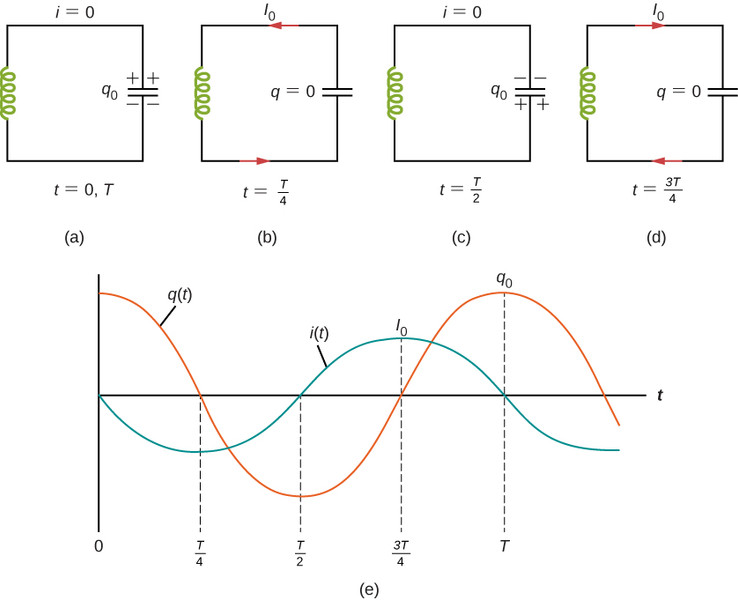
- Start ( ): Capacitor has maximum charge , current . All energy in .
- Capacitor discharges → current grows → magnetic field builds.
- Quarter period ( ): Capacitor momentarily has , current is maximum. All energy in .
- Inductor keeps current flowing, charging the capacitor with opposite polarity.
- Half period ( ): Capacitor again has maximum charge, but with reversed polarity, and current is zero. The process then repeats.
On the graph, notice that and are sinusoidal and out of phase. When charge is maximum, current is zero. When current is maximum, charge is zero.
This is the electrical version of a mass-spring system:
| Mechanical | Electrical |
|---|---|
| Position | Charge |
| Velocity | Current |
| Mass | Inductance |
| Spring constant |
That analogy helps a lot on FRQs when you’re asked to “describe the motion.”
2. Energy Conservation and Maximum Current
Because energy is conserved, the maximum current occurs when all the initial capacitor energy has moved into the inductor.
Set initial capacitor energy equal to maximum inductor energy:
Solve for :
Or in terms of maximum charge :
Key relationships you should be able to say quickly:
- When is maximum →
- When is maximum →
- Increasing increases
- Increasing decreases
A common quiz trap is forgetting that the maximum current does not occur when the capacitor is fully charged. It occurs when the capacitor is fully discharged.
3. LC Circuits as Simple Harmonic Motion
Apply Kirchhoff’s loop rule to the circuit:
Voltage across inductor + voltage across capacitor
Since , substitute:
Rewriting:
This matches the SHM form:
So,
That’s the key derivation they like to see on FRQs. You identify the differential equation and compare it to SHM.
Time Dependence
Charge behaves sinusoidally:
Current is its derivative:
So charge and current are 90° out of phase. When is at a maximum or minimum, . When is at a maximum or minimum, .
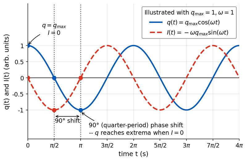
Charge and current in an LC circuit, 90° phase shift
Use this graph to connect the math to the physics. At the points where the blue curve for reaches a peak, the red dashed curve for crosses zero. A quarter period later, the current reaches its maximum magnitude as the charge passes through zero.
Also notice energy depends on squared quantities, so energy oscillates at twice the frequency of charge and current.
4. Angular Frequency and Period
From the differential equation:
Frequency and period:
What changes the oscillation rate?
- Larger → slower oscillation
- Larger → slower oscillation
- Amplitude does not affect frequency
This independence from amplitude mirrors mechanical SHM. If you double the initial voltage, you double the amplitude of and , but stays the same. That idea shows up often in conceptual multiple-choice questions.
