Topic 5.3 Notes – Torque
1. What Torque Is
If force measures how strongly something translates, torque measures how strongly something rotates about a chosen pivot.
Later you’ll use but right now the focus is identifying and describing individual torques.
Vector definition
- is the position vector from the pivot to where the force is applied
- is the applied force
- The pivot must be specified. Change the pivot and the torques change.
Magnitude
- is the distance from pivot to force application point
- is the angle between and
Only the perpendicular component of the force contributes.
Special cases:
- → maximum torque →
- or → zero torque
Units are . Same units as energy, but torque is a vector, not a scalar.
2. Components of the Torque Formula
Position Vector
This is where students mess up.
- It always starts at the pivot
- It ends at the point where the force is applied
- Direction matters for the cross product
If you draw it backward, your torque direction will be wrong.
Perpendicular Force Component
From :
where .
So you can either:
- Break the force into components and use the perpendicular one, or
- Use directly.
Same physics either way.
Lever Arm (Moment Arm)
There’s an equivalent and often easier method.
The lever arm is the perpendicular distance from the pivot to the line of action of the force.
And since , this matches the earlier formula.
Here’s what that geometry looks like in a typical setup with an angled force:
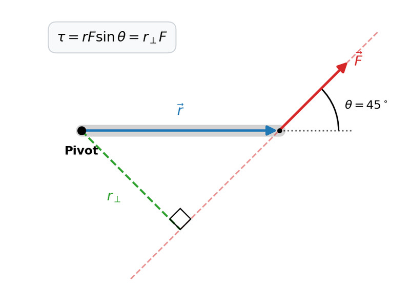
Torque geometry: , , and lever arm
Notice how the dashed perpendicular from the pivot to the dashed line of action gives . That distance alone determines how effective the force is at causing rotation.
Important consequences:
- A small force far from the pivot can equal a large force close in.
- If the force acts through the pivot, the lever arm is zero → no torque.
- If the force is directed straight toward or away from the pivot, .
AP problems often hide this in geometry. Always look for that perpendicular distance.
3. Direction of Torque and the Cross Product
Torque direction comes from the cross product.
For any :
- Magnitude is
- Direction is perpendicular to the plane containing them
So is perpendicular to both and .
Right-hand rule
The diagram below shows the cross product and the hand motion that determines its direction.

Right-hand rule for the cross product
How to apply it for torque:
- Point fingers along
- Curl toward
- Your thumb gives the direction of
In 2D:
- Out of the page → counterclockwise → usually positive
- Into the page → clockwise → usually negative
On most quizzes and FRQs, torque becomes a signed scalar. You decide a sign convention and stay consistent.
4. Drawing Force Diagrams for Torque Problems
A torque diagram is basically a free-body diagram with locations included.
You must show:
- The rigid object
- The pivot point
- Every force
- Where each force is applied
If you leave out location, you can’t determine torque.
For each force, ask:
- Does it pass through the pivot? → zero torque
- Is it parallel to ? → zero torque
- Does it try to rotate CW or CCW?
Example thinking:
- Weight at the end of a horizontal beam about a wall hinge → clockwise.
- Normal force at the hinge → zero torque about that hinge.
The exam loves pivots chosen to eliminate unknown forces. If you pick the pivot at a hinge, hinge forces produce zero torque automatically.
5. Strategy for Identifying Torques
When analyzing a rigid system:
- Choose a pivot.
- Draw to each force.
- Determine sign (CW or CCW).
- Compute with or .
Changing pivots changes individual torques, but the physical rotation of the object doesn’t change.
Your goal in this topic is speed and clarity. You should be able to look at a diagram and immediately classify every force as positive torque, negative torque, or zero torque.
