Topic 11.2 Notes – Simple Circuits
1. What a Simple Circuit Is
A circuit is a set of connected electrical elements that form one or more closed conducting loops. Charges move because a source (like a battery) creates an electric field that pushes them through the loop.
On the AP exam, assume conventional current flows from the positive terminal to the negative terminal unless told otherwise. (Electrons actually move the other way, but we don’t use that direction in circuit diagrams.)
A few structural ideas matter:
- A loop is any complete closed conducting path.
- A circuit can have one loop or multiple loops.
- A single component can be part of more than one loop.
- If there is no closed loop, there is no sustained current.
That last point is the foundation for everything else in this topic.
2. The Three Circuit States
When you’re asked to “describe the behavior of the circuit,” you’re usually deciding which of these three states you’re looking at.
Closed Circuit
A closed circuit has a complete conducting path from one battery terminal to the other.
- Charges can flow continuously.
- Current exists in that loop.
- The current continues as long as the loop stays intact.
Closed loop → current flows.
Open Circuit
An open circuit has a break somewhere in the loop. This could be:
- An open switch
- A disconnected wire
- A burned-out bulb (broken filament)
Key consequences:
- No complete path → no current anywhere in that loop.
- There may still be a potential difference across the break.
In a single series loop, one break stops current everywhere in that loop. That’s a classic AP multiple-choice trap.
Short Circuit
A short circuit is when charges flow through a path with negligible resistance and essentially no change in potential difference along that path.
- Current bypasses other components.
- The low-resistance path “wins.”
- Can produce very large currents in real systems.
Here’s a clean comparison:
| State | Loop Complete? | Current? | What Happens? |
|---|---|---|---|
| Closed | Yes | Yes | Normal operation |
| Open | No | No | Current stops in that loop |
| Short | Yes (low R path) | Yes (often large) | Bypasses intended elements |
3. Common Circuit Elements and Their Roles
You need to recognize these instantly in a schematic. The chart below shows the standard symbols you are expected to know for the AP exam.
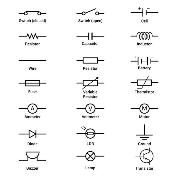
Common circuit schematic symbols
Wires
- Ideal wires have negligible resistance.
- Every point along the same ideal wire is at the same potential.
Battery (Voltage Source)
- Provides potential difference (emf).
- Long line = positive terminal.
Resistor
- Limits current.
- Converts electrical energy to thermal energy.
Lightbulb
- Acts like a resistor.
- If the filament breaks → open circuit.
Capacitor
- Stores charge and energy in an electric field.
- Can temporarily affect current when charging or discharging.
Switch
- Open → breaks the loop.
- Closed → completes the loop.
Ammeter
- Measures current.
- Placed in series.
- Ideal: zero resistance (so it doesn’t change the circuit).
Voltmeter
- Measures potential difference between two points.
- Placed in parallel.
- Ideal: infinite resistance.
Variable components are shown with a diagonal arrow across the standard symbol, as in the variable resistor shown above.
4. Circuit Schematics and Physical Arrangement
A schematic diagram shows how components are electrically connected, not how they physically look on a table.
Important ideas:
- Rearranging wires without changing connections does not change behavior.
- Two points connected by ideal wire are at the same potential.
- A single element can belong to multiple loops in multi-loop circuits.
AP questions love redrawing the same circuit in a confusing way.way. If the connections are the same, the physics is the same.
5. Predicting Basic Circuit Behavior
When analyzing quickly:
- Is there a closed loop?
- If not, no current.
- Is there a short path bypassing something?
- Which components share the same loop?
- If one element fails, does it open a loop?
Patterns to remember:
- In a single series loop, one open element shuts everything off.
- Current follows the available conducting paths.
- Meters must be connected correctly or they change the circuit behavior.
When writing explanations, use physical reasoning:
“Because the switch is open, there is no closed conducting path, so charges cannot flow and the current is zero everywhere in that loop.”
That’s the level of clarity graders look for.
