Topic 13.4 Notes – Images Formed by Lenses
1. How Lenses Form Images
A thin lens refracts light at its two surfaces. What matters is how rays behave relative to the principal axis and the focal points (there is one on each side of the lens).
Converging (Convex) Lens
- Thicker in the middle.
- Parallel rays refract and meet at a focal point on the far side.
- Focal length .
- Can form real or virtual images depending on object position.
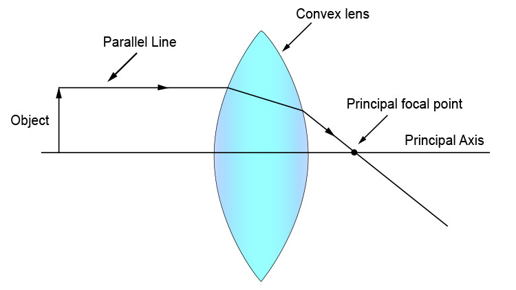
Ray diagram for a converging (convex) lens
In the diagram, a ray that starts parallel to the principal axis refracts through the focal point on the opposite side of the lens. Physically, the lens bends light inward so rays that started parallel actually cross.
Diverging (Concave) Lens
- Thinner in the middle.
- Parallel rays spread out after passing through.
- Rays diverge as if they came from a focal point on the same side as the object.
- Focal length .
- Forms only virtual images for real objects.
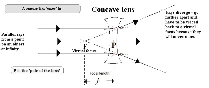
Ray diagram for a diverging (concave) lens
Notice in the diagram that the refracted rays spread out, and their dashed backward extensions meet at the labeled virtual focus on the object’s side. The focal point here is virtual. Light does not pass through it. It only appears to.
Real vs Virtual Images
A real image forms when refracted rays actually intersect at a point.
- Can be projected onto a screen.
- For lenses, real images are inverted.
A virtual image forms when rays diverge but appear to come from a point when extended backward.
- Cannot be projected onto a screen.
- Typically upright.
On free-response, you must state all characteristics: location, real/virtual, upright/inverted, enlarged/reduced.
2. The Thin-Lens Equation and Sign Conventions
The location of the image depends on object distance and focal length.
- = object distance
- = image distance
- = focal length
Sign Conventions (this is where people lose points)
- converging lens
- diverging lens
- real object (almost always the case)
- real image (opposite side from object)
- virtual image (same side as object)
Each lens has two focal points, symmetric on both sides of the lens.
Quick Example
Suppose and .
So , positive → real image.
If you ever get a negative , that automatically means virtual.
3. Magnification and Image Orientation
The magnification equation connects size and orientation:
- → upright
- → inverted
- → enlarged
- → reduced
Using the example above:
Negative → inverted.
Magnitude 2 → twice as tall.
So the full description would be:
Real, inverted, enlarged (factor of 2), 36 cm from the lens.
Notice the pattern:
- Real images → → → inverted.
- Virtual images → → → upright.
That connection shows up constantly in multiple-choice reasoning questions.
4. Ray Diagrams for Lenses
Ray diagrams let you determine everything without algebra. Here is a standard example for a converging lens with the object placed outside the focal length.

Principal rays for a converging lens
The Three Principal Rays
- Parallel ray
- Converging → through far focal point
- Diverging → appears from near focal point
- Central ray
- Through lens center, no bending
- Focal ray
- Converging → through near focal point, exits parallel
- Diverging → aimed toward far focal point, exits parallel
Where the refracted rays intersect is the image. In the diagram above, the three refracted rays meet on the right side of the lens, forming a real, inverted image. If they only intersect when extended backward with dashed lines, the image is virtual.
Converging Lens Outcomes
Object position determines image:
- Beyond → real, inverted, reduced
- At → real, inverted, same size
- Between and → real, inverted, enlarged
- At → no image (rays exit parallel)
- Inside → virtual, upright, enlarged
Diverging lens → always virtual, upright, reduced.
On the AP exam, you might be shown a partially drawn ray diagram and asked to finish it or describe the image. Always trace at least two rays clearly.
