Topic 11.5 Notes – Compound Direct Current (DC) Circuits
1. Equivalent Resistance in Compound Circuits
In any DC circuit, you can replace a group of resistors with a single equivalent resistance that draws the same total current from the battery.
This works because of:
- Conservation of charge → current splits and recombines but is conserved.
- Conservation of energy → total energy per charge from the battery equals total energy lost across resistors.
- Ohm’s Law .
If you can reduce a messy circuit to one resistor, you can immediately find the total current using
A compound circuit just means it contains both series and parallel parts.
2. Series and Parallel Connections
Series Connections
In a series connection, charge has only one path. Any charge that goes through one resistor must go through all of them.
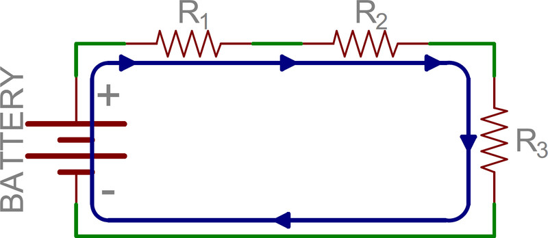
Single-loop series circuit
In the single loop above, notice how the current follows one continuous path through , , and .
Key facts:
- Same current through each resistor.
- Voltage divides among resistors.
- Equivalent resistance:
Why does resistance add? Each resistor adds more opposition in the single path, so total resistance increases.
If you add more resistors in series:
- increases
- Total current (for fixed battery voltage) decreases
Parallel Connections
In a parallel connection, charge has multiple paths between the same two points.
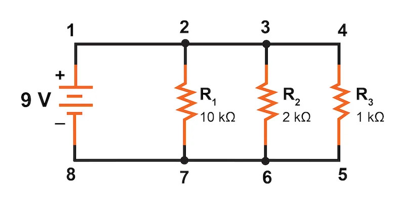
Three resistors in parallel across a 9 V battery
Each resistor in the diagram is connected across the same top and bottom nodes, so they all share the full 9 V.
Key facts:
- Same voltage across each branch.
- Current splits.
- Lower resistance branch → larger current.
- Total current = sum of branch currents.
Equivalent resistance:
Important result:
Adding parallel branches gives charges more paths, which makes it easier for current to flow, so total resistance decreases.
3. How to Analyze Compound Circuits
When circuits mix series and parallel, reduce them step by step.
- Find a clear series or parallel group.
- Series → no branching between them.
- Parallel → share the same two nodes.
- Replace that group with its .
- Redraw the simplified circuit.
- Repeat until one resistor remains.
- Use .
- Work backward:
- Series → same current.
- Parallel → same voltage.
On free-response, graders want to see that you identify why something is series or parallel, not just plug numbers into formulas.
4. Real Batteries and Resistive Wires
Most AP problems assume ideal components unless told otherwise.
Ideal assumptions
- Ideal battery → zero internal resistance.
- Ideal wires → zero resistance.
- Terminal voltage = emf .
Wire resistance can usually be ignored because it’s much smaller than resistor values in the circuit. It only matters if the wire is very long, very thin, or the rest of the circuit has very small resistance.
Battery with Internal Resistance
A real battery behaves like an ideal emf source in series with a small internal resistance, often labeled .
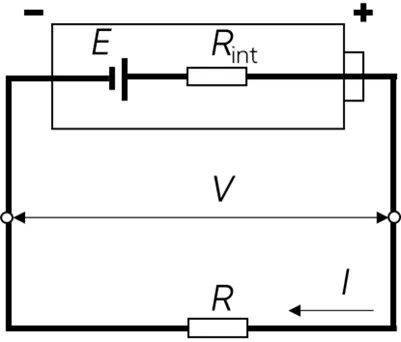
Battery modeled as an emf source in series with internal resistance
That internal resistance is in series with whatever external resistor is connected.
Total resistance:
Current:
Terminal voltage:
When current flows, some energy is lost as heat inside the battery. So terminal voltage is less than emf.
If (open circuit), then terminal voltage equals emf.
As current increases, the internal drop increases, and terminal voltage decreases. That cause-and-effect explanation shows up often in conceptual questions.
5. Measuring Current and Voltage
Meters are part of the circuit, so they can affect it.
Ammeters
- Measure current.
- Must be placed in series.
- Ideal ammeter → zero resistance.
If it had resistance, it would increase total series resistance and reduce current.
Voltmeters
- Measure potential difference.
- Must be placed in parallel.
- Ideal voltmeter → infinite resistance.
If it allowed current through, it would change how current distributes in the circuit.
AP only expects qualitative reasoning about nonideal meters. Unless stated otherwise, assume meters are ideal.
