Topic 14.8 Notes – Double-Slit Interference and Diffraction Gratings
1. What a Double-Slit Interference Pattern Is
When monochromatic light (one wavelength ) hits two narrow slits separated by distance , each slit acts like a new wave source. The waves spread out (diffraction) and overlap (interference) on a distant screen.

Young’s double-slit interference pattern
On the screen you see:
- A series of bright and dark vertical bands
- A bright central maximum at the center (labeled in the figure)
- A symmetric pattern on both sides with higher-order maxima ()
Bright bands come from constructive interference.
Dark bands come from destructive interference.
The key idea behind all of it is path length difference .
If one wave travels a slightly longer distance than the other, they may arrive in or out of phase. The geometry of the slits gives:
- = slit separation
- = angle from the central axis (straight ahead from the slits)
- determines whether the waves reinforce or cancel
Young’s double-slit experiment showed this pattern clearly. A particle-only model of light cannot explain stable dark bands.
2. Conditions for Bright and Dark Fringes
Everything comes from comparing path difference to wavelength.
Constructive Interference (Bright Fringes)
Waves arrive in phase when:
- These are the maxima
- They are evenly spaced if we consider interference alone
Destructive Interference (Dark Fringes)
Waves arrive out of phase when:
These are the dark bands between bright ones.
On quizzes, you’re often asked to explain in words. A strong explanation sounds like this:
“Bright fringes occur when the path difference equals an integer multiple of the wavelength, so the waves arrive in phase and interfere constructively.”
Small-Angle Approximation and Screen Geometry
If the screen is far away, angles are small. Then:
Substitute into the bright-fringe equation:
- = distance from center to the mth bright fringe
- = distance to screen
From this relationship:
- Larger → wider fringe spacing
- Larger → wider spacing
- Larger → fringes get closer together
FRQs love “what happens if…” questions. Always look at proportionality.
3. Interference Pattern vs Diffraction Envelope
If slits had zero width, you’d get evenly spaced bright lines with equal intensity. Real slits have width, so each slit also produces a single-slit diffraction pattern.
The actual result is:
- Many evenly spaced interference maxima
- All contained inside a broader diffraction envelope
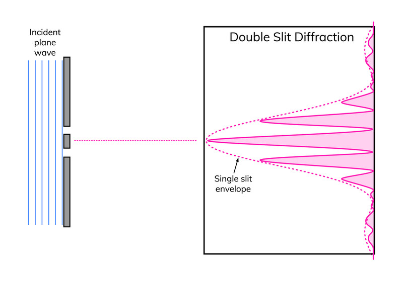
Double-slit interference within a single-slit diffraction envelope
In the diagram, the narrow bright peaks are the interference maxima. The dashed outer curve shows the broader single-slit diffraction envelope that controls their overall intensity.
What this means physically:
- Central maximum is brightest
- Outer maxima decrease in intensity
- Some interference maxima can be missing if they land at a diffraction minimum
If you’re interpreting a diagram on an MCQ, evenly spaced peaks tell you interference. Gradual intensity drop tells you diffraction is also present.
4. Diffraction Gratings
A diffraction grating is many evenly spaced parallel slits.
Each slit produces a diffracted wave. With hundreds or thousands of slits, the interference becomes extremely sharp.
The equation is the same:
But compared to double slits:
- Maxima are narrower and brighter
- Minima are darker
- Much better for measuring wavelength
If given “lines per meter,” remember:
Students often forget that step and plug in the wrong .
5. White Light and Color Separation
White light contains many wavelengths.
For :
All wavelengths overlap, so the central maximum is white.
For higher orders:
Longer wavelength means a larger angle.
So:
- Red (longest visible wavelength) appears farthest from center
- Violet appears closest to center

White light diffraction pattern from a grating
The diagram shows the white central maximum and the first- and second-order spectra on both sides. Each order produces a full rainbow. Higher orders spread out more and may overlap.
